Computer Network / कंप्यूटर नेटवर्क
  • A network is a collection of interconnected devices — computers, mobiles, servers, printers, etc. — linked by wired or wireless communication paths to share data, resources and services.
  • Key elements: Nodes • Links/Transmission Media • Protocols • Resources.
  • Nodes include computers, laptops, smartphones, printers and special devices such as servers.
  • Transmission media can be wired (twisted pair, coaxial, optical fiber) or wireless (Wi‑Fi, Bluetooth, satellite, infrared).
  • Protocols listed early in the chapter include TCP/IP, HTTP/HTTPS and SMTP/IMAP.
Source visual: a basic network with Internet, firewall, wireless router and endpoint devices
Source visual: key components of a computer network
Source visual: guided and unguided transmission media
Network Hardware at a Glance

Router

Connects different networks such as LAN ↔ Internet.

Switch

Connects multiple devices within a LAN.

Hub

Basic multi-device connector; broadcasts traffic.

Access Point

Provides wireless connectivity.

Firewall

Monitors/controls traffic for security.
Source visual: hardware components in a network
Source visual: common network device types
History of Computer Networks / इतिहास
1950sMainframe + terminal based early networking
1969ARPANET; four universities; source notes first message “LO”
1970sTCP/IP by Vint Cerf & Bob Kahn; source notes 1973 international link
1980sEthernet expansion; DNS (1983); WWW (1989)
1990sPublic/commercial Internet; websites, email, e-commerce; Wi‑Fi (1997)
2000s–PresentBroadband, 4G/5G, cloud, IoT, social media, AI
Source visual: TCP/IP pioneers shown in the PDF
Source visual: Tim Berners-Lee image in the PDF
Source visual: DNS server concept
Source visual: networking / Internet development timeline graphic
Source visual: 5G-enabled IoT / modern network concepts
Source-bound
Dates, labels and historical claims here follow the supplied PDF; no outside verification or correction has been mixed into this chapter.
Classification of Networks / नेटवर्क का वर्गीकरण
  • The chapter lists classification by geographical area, topology, ownership and transmission medium.
  • The detailed source material in this chapter primarily expands geographical-area classification and topology classification.
TypeFull FormCoverageTechnology / DevicesSource Example
PANPersonal Area Network~10 mBluetooth, Infrared, USBPhone ↔ headset / smartwatch
LANLocal Area NetworkFew kmEthernet, Wi‑FiSchool, office, computer lab
CANCampus Area NetworkCampus / premisesMultiple LANsUniversity departments
MANMetropolitan Area Network10–50 kmFiber, microwave, leased linesCity Wi‑Fi, cable TV, bank branches
WANWide Area Network1000s kmRouters, modems, satellitesInternet, IRCTC, ATM networks
SANStorage Area NetworkStorage-centricHigh-speed server-storage linksData center / bank storage
PAN & LAN

PAN — Personal Area Network

Range: source says up to ~10 m.
Devices: laptop, smartphone, smartwatch, Bluetooth printer/headset.
Tech: Bluetooth, IR, USB.
Pros: easy setup, personal use, few/no cables.
Limits: limited range and number of devices.

LAN — Local Area Network

Coverage: school, office, building; source says up to a few km.
Tech: Ethernet, Wi‑Fi.
Pros: high speed, easy management/security, low error rate.
Limit: limited coverage and initial setup cost.
Source visual: Local Area Network
Source visual: LAN with switch/router connections
CAN, MAN, WAN & SAN

CAN

Connects multiple LANs in a campus, industrial area or organization premises. Advantage: efficient inter-department communication and centralized resources.

MAN

City/metropolitan network; source gives 10–50 km. Uses fiber, microwave or leased lines. Examples: city Wi‑Fi, cable TV, bank branches.

WAN

Country/continent scale; source says 1000s km. Routers/modems/satellites. Internet = source’s largest WAN example.

SAN

High-speed server-to-storage network. Examples: data centers, banks, cloud storage backends.
Source visual: Campus Area Network
Source visual: Metropolitan Area Network
Source visual: Wide Area Network
Source visual: Storage Area Network
⚠ EXAM TRAP
PAN ≠ LAN ≠ CAN ≠ MAN ≠ WAN ≠ SAN. Remember the progression: Personal → Local → Campus → Metropolitan → Wide; SAN is storage-oriented rather than simply “next larger area”.
Topology / टोपोलॉजी
  • Network topology is the arrangement/layout of computers, cables and components and how nodes/links are organized.
  • Physical topology: actual physical connections of devices and cables.
  • Logical topology: how data flows among network devices.
  • Six common types listed: Bus, Star, Ring, Mesh, Tree, Hybrid.
Source visual: common network topologies
Core Topology Terms

Node

Any connected device that can send/receive data.

Link

Communication path between two nodes; wired or wireless.

Backbone

Main central cable/channel carrying most traffic.

Segment

Part of a network separated by switches/routers.

Path

Sequence of links/nodes from source to destination.

Hop

One movement from one node to the next.

Redundancy

Multiple paths so another route can be used if one fails.

Collision

Signals overlap when multiple devices send simultaneously on same medium.

Token

Small control frame passed around a Ring network.

Fault Tolerance

Network keeps working even when components fail.

Scalability

Ease of adding nodes/links without harming performance.

Node Degree

Number of direct connections a node has.
Performance Terms

Throughput

Successfully transmitted data per unit time; source measures in Mbps.

Latency

Delay between sending and receiving data; source notes satellite networks can have high latency.

Bandwidth

Maximum data transfer capacity, commonly Mbps/Gbps.

Efficiency

Useful data transmission ÷ total transmission.
Source visual: throughput formula
Data Flow

Simplex

One-way only.
Example: Keyboard → computer/monitor in source examples.

Half Duplex

Both directions, but one at a time.
Example: Walkie-talkie.

Full Duplex

Both directions simultaneously.
Example: Telephone.
Bus Topology / बस टोपोलॉजी
  • All nodes connect to one central Bus/Backbone cable.
  • Data placed on the bus travels in both directions; each node checks the destination address.
  • Terminators at both ends prevent signal reflection; drop lines connect nodes to the bus.
  • Source examples: early Ethernet 10Base2/10Base5, small coaxial-cable office networks.

Advantages

Easy installation • less cable than star • suitable for small networks • easy node expansion.

Disadvantages

Main cable failure stops network • troubleshooting difficult • limited length/nodes • collisions/reflection • heavy-load slowdown.
Source visual: Bus topology with terminators
Ring Topology / रिंग टोपोलॉजी
  • Each node connects to exactly two others, forming a closed loop.
  • Data moves around the ring to destination; source discusses Token Passing for access control.
  • Only the node holding the token can transmit; after sending it releases/passes the token.
  • Types: Single Ring (one direction) and Dual Ring (two rings / bidirectional).
  • Source examples: IBM Token Ring and FDDI.
Source visual: Ring topology and token passing
Source visual: Single Ring vs Dual Ring

Advantages

Orderly communication • no collisions in token access • equal access • token absence can help fault identification.

Disadvantages

One node failure may disrupt network • adding/removing nodes difficult • troubleshooting/maintenance complex.
Star Topology / स्टार टोपोलॉजी
  • Every node connects to a central hub, switch or router; nodes are not directly connected to each other.
  • Source examples: Ethernet LANs, Wi‑Fi router home networks, office switch networks.

Advantages

Easy install/manage • one node failure does not affect others • easy troubleshooting • dedicated cable gives good performance • scalable.

Disadvantages

Central hub failure stops network • more cable than bus • higher installation cost • hub can bottleneck under heavy load.
Mesh Topology / मेश टोपोलॉजी
  • Nodes are connected directly or through multiple paths; alternate routes provide redundancy and fault tolerance.
  • Types: Full Mesh and Partial Mesh.
  • Source applications: military communication, Internet backbone routers, mission-critical control systems.
Full Mesh connections: n(n − 1) / 2
Source visual: Full Mesh vs Partial Mesh
Source visual: full-mesh connection formula with 5-node example

Advantages

High reliability/redundancy • one-link failure does not affect others • high traffic support • high security • alternate paths.

Disadvantages

Very expensive • many cables/ports • complex install/maintenance • not suitable for small networks.
Tree & Hybrid Topology

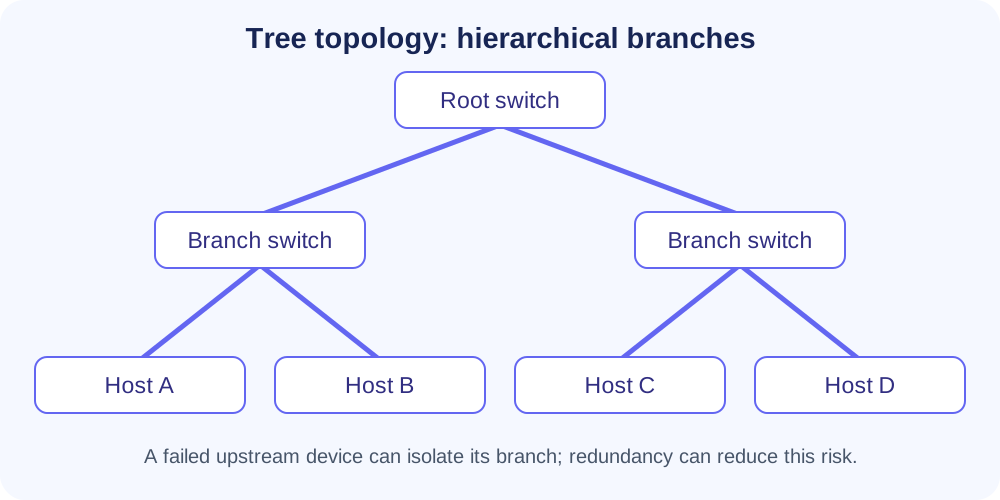
Tree

The source lists Tree Topology as hierarchical in comparison tables and describes it as scalable with moderate reliability/cost. A full standalone Tree explanation is not present in the supplied chapter pages, so no extra details are added here.

Hybrid

Combination of two or more topologies such as Bus, Star, Ring, Mesh or Tree. Used when different departments/sub-networks use different layouts and are joined via hub/router/backbone.
Source visual: Hybrid topology combining Star, Ring and Bus
Hybrid — Source Pros & Cons
Pros: highly flexible/scalable, combines strengths, reliable, suitable for large/complex networks, easy to add nodes/topologies.
Cons: expensive, complex design/maintenance, advanced management, difficult troubleshooting, more hardware.
Topology Comparison
FeatureTreeStarBusRingMesh
StructureHierarchicalCentral hubSingle lineCircularFully connected
ReliabilityModerateMediumLowMediumHigh
CostMediumMediumLowMediumVery high
ScalabilityHighMediumLowLowDifficult
Fault ToleranceGoodMediumPoorPoorExcellent
Source table
This comparison follows the PDF’s table wording. It is reproduced as source material rather than normalized with outside networking references.
Network Protocol / नेटवर्क प्रोटोकॉल
  • A network protocol is a set of rules/conventions that determines how data is transmitted and received between computers.
  • Purpose: reliable communication; definition of data format, timing, error checking and compression.
  • Main source categories: Communication, Security, Management, Routing.
HTTP vs HTTPS

HTTP

Layer: Application
Port: 80
Transfers web pages/resources between browser and server. Source notes plain-text/no encryption.

HTTPS

Layer: Application
Port: 443
Secure HTTP using SSL/TLS; source describes certificate verification and encrypted connection.
HTTPURL → Browser request → Server → HTTP response → Browser display
HTTPSURL → Port 443 → SSL certificate → CA verification → Encrypted connection → Secure data
⚠ QUICK DIFFERENCE
HTTP = 80, no encryptionHTTPS = 443, SSL/TLS encryption + lock indicator according to the source.
Application & Common Protocols
ProtocolCategoryLayerPortMain Function
HTTPCommunicationApplication80Web data transfer
HTTPSSecurityApplication443Secure web transfer (SSL/TLS)
FTPCommunicationApplication20, 21File transfer
SMTPCommunicationApplication25 (source also notes 587 secure)Send email
POP3CommunicationApplication110Receive/download email
IMAPCommunicationApplication143Manage mail on server
DNSCommunicationApplication53Domain name → IP address
DHCPCommunicationApplication67, 68Automatic IP assignment
TELNETCommunicationApplication23Remote command-line access; source marks insecure
SSHSecurityApplication22Secure remote login
SNMPManagementApplication161Monitor network devices
ICMPManagementNetworkDiagnostics/error reporting; ping
RIPRoutingNetwork520Path selection by hop count
OSPFRoutingNetwork89Link-state best path
BGPRoutingNetwork179Routes between networks / ISPs
Security, Transport & Network Protocols

SSL/TLS

Source: Application layer; HTTPS security on port 443; encrypts browser-server data.

SSH

Application layer, port 22; secure encrypted remote login.

IPSec

Network layer; secures IP packets; source example: VPN.

TCP

Transport layer; reliable, connection-oriented, ordered; retransmits lost packets.

UDP

Transport layer; fast, connectionless, no delivery/order guarantee; streaming/gaming/VoIP.

IP

Network layer; logical addressing and routing of packets.

ARP

Data Link layer; maps local-network IP addresses to MAC addresses.

ICMP

Network layer; diagnostics and error/control messages; ping example.

RARP

Source summary: reverse mapping MAC → IP; booting diskless systems.
Other Protocol Families in Source
Network Access / Data Link
Ethernet — LAN wiring/signalingPPP — Point-to-PointHDLC — WAN error-free transferFrame Relay — WAN transferATM — fixed-size cells
Routing
RIP — hop countOSPF — link-stateBGP — between ISPsIGRP / EIGRP — source labels Cisco proprietary
Layered Network Architecture
  • Networking is divided into functional layers; each layer performs specific tasks, serves the layer above and receives services from the layer below.
  • Purpose: simplify design/troubleshooting, promote interoperability, modular upgrades and clear interfaces.
  • Main models listed: OSI (7 layers) and TCP/IP (4 or 5 layers).
Source visual: seven layers of OSI
Source visual: OSI vs TCP/IP mapping
OSI — 7 Layers
LayerNameMain Function in SourceExamples
7ApplicationNetwork services directly to end-user applicationsHTTP, FTP, SMTP, DNS, Telnet
6PresentationTranslation, formatting, encryption/decryption, compressionSSL/TLS, JPEG, MPEG, ASCII, Unicode
5SessionEstablish, maintain, terminate sessions; synchronization/dialog controlNetBIOS, RPC
4TransportEnd-to-end delivery, segmentation/reassembly, flow/error controlTCP, UDP
3NetworkLogical addressing, packet routing/forwarding, path selectionRouter, IP, ICMP, OSPF, RIP
2Data LinkFrames, error detection/correction, flow control, MAC addressingSwitch, Bridge, Ethernet, ARP
1PhysicalRaw bits, media, cables/connectors, voltage/signal timingCables, fiber, hubs, repeaters
Source visual: OSI data units / layer responsibilities
OSI Working Example — Sending Email
7 ApplicationEmail sent using SMTP
6 PresentationMessage encrypted/formatted
5 SessionSession created
4 TransportMessage segmented (TCP)
3 NetworkIP routing
2 Data LinkFrames + MAC addresses
1 PhysicalBits over cable/wireless
At Receiver
The source notes that the process is reversed — bottom to top.
OSI Pros & Cons

Advantages

Standardized model • easy understanding/troubleshooting • modular design • vendor interoperability.

Disadvantages

Theoretical model • duplicated functions across layers • implementation described as more complex/slower than simpler TCP/IP model.
Network Devices / नेटवर्क उपकरण

Hardware components that connect systems and help with data communication, routing, filtering, security and traffic control.

Source CategoryOSI LayerExamples
Layer 1 DevicesPhysicalHub, Repeater, Modem
Layer 2 DevicesData LinkSwitch, Bridge
Layer 3 DevicesNetworkRouter, Gateway
Source visual: common types of network devices
Source visual: Hub broadcasting to connected devices
Device Functions — Detailed

Router — Layer 3

Connects LAN/WAN/Internet; finds best path; source says it can assign IP via DHCP and provide firewall-based security.

Switch — Layer 2

Connects LAN devices; uses MAC addresses; forwards to intended device; reduces congestion; can support VLANs.

Hub — Layer 1

Broadcasts to all ports; no filtering/intelligence; source notes congestion/collision and lower security.

Modem

Modulator-Demodulator; source describes digital ↔ analog conversion for telephone/cable communication; DSL/cable/fiber types.

Access Point

Connects wireless devices to a wired network using Wi‑Fi; extends wireless coverage.

Repeater

Regenerates/strengthens weak signals to extend distance and coverage.

Bridge — Layer 2

Connects network segments and filters traffic using MAC addresses.

Gateway

Connects networks using different protocols; acts as protocol translator.

Firewall

Monitors and controls incoming/outgoing traffic using security rules.
⚠ HUB vs SWITCH vs ROUTER
Hub: Layer 1, broadcasts • Switch: Layer 2, MAC-based forwarding • Router: Layer 3, routes between networks using logical/IP addressing.
Firewall / फ़ायरवॉल
  • Firewall = hardware or software that monitors and controls incoming/outgoing network traffic using security rules.
  • Acts as a barrier between trusted internal networks and untrusted external networks such as the Internet.
  • Functions listed: traffic filtering • attack protection • access control • monitoring/logging • network segmentation.
Source visual: firewall between a secure private LAN and external network
Types of Firewall

Packet Filtering

Checks source/destination IP, ports, protocols; fast but limited security.

Stateful Inspection

Tracks active connection state/context; more security than basic packet filtering.

Proxy Firewall

Application-level intermediary; high security but slower performance.

Circuit-Level Gateway

Session-layer; checks TCP handshakes/connection legitimacy, not packet contents.

NGFW

Traditional filtering + intrusion prevention, deep packet inspection, application awareness.

Hardware Firewall

Physical device between network and gateway; common in organizations.

Software Firewall

Installed on individual computers/servers to protect specific devices.

Cloud Firewall

Cloud-hosted scalable/flexible firewall service.
Proxy Server / प्रॉक्सी सर्वर
  • Intermediary between a client and the Internet: client sends request to proxy → proxy checks rules → forwards to destination → receives response → returns it to client.
  • Source purposes: security, usage control, privacy and performance through caching.
  • If cached content exists, proxy may return it directly without contacting destination server.
Source visual: Proxy Server between device and Internet
1Client request
2Proxy checks filter/auth/logging rules
3Allowed request forwarded
4Destination responds
5Proxy returns response / cache
Types of Proxy Servers

Forward Proxy

Between client and Internet; organization controls/monitors access; can hide client IP.

Reverse Proxy

In front of web servers; handles client requests; load balancing, security, caching.

Transparent Proxy

Does not hide client IP; used for content filtering/caching without user configuration.

Anonymous Proxy

Hides client IP; moderate privacy.

High-Anonymity / Elite

Highest privacy in source description; completely hides client IP.

SOCKS Proxy

Lower-level than HTTP proxy; can handle varied traffic such as email, file transfers and torrents.
Network Addressing System / नेटवर्क एड्रेसिंग
  • Structured method for uniquely identifying devices so packets reach the correct destination.
  • Each packet contains source and destination addresses.
  • Source distinguishes: routers use logical addresses across networks; switches rely on physical addresses within a local network.
Types of Network Addresses

IP Address

Logical address. IPv4: 32-bit, e.g. 192.168.1.1. IPv6: 128-bit, e.g. 2001:0db8::1. Can be static or DHCP-assigned dynamic.

MAC Address

Physical NIC address assigned by manufacturer. Source: 48-bit hexadecimal, e.g. 00:1A:2B:3C:4D:5E.

Port Address

Identifies a process/service. Range 0–65535: well-known 0–1023, registered 1024–49151, dynamic 49152–65535.

Broadcast Address

Sends to all devices in a network. Source example: IPv4 subnet’s last address, e.g. 192.168.1.255.

Multicast Address

Sends to selected group. Source IPv4 range: 224.0.0.0–239.255.255.255.

Network Address

Identifies the entire network. Example: in 192.168.1.0/24, 192.168.1.0 is the network address.
Addressing + Protocol Recall

DHCP

Automatically assigns IP addresses when devices join a network.

ARP

Maps local-network IP addresses to MAC addresses.
Chapter Boundary
This source chapter ends with network addressing. The next PDF page begins Cyber Security.
Ultra-Fast Revision

Basics

Nodes • Links • Protocols • Resources

Area Types

PAN • LAN • CAN • MAN • WAN • SAN

Topologies

Bus • Star • Ring • Mesh • Tree • Hybrid

Performance

Throughput • Latency • Bandwidth • Reliability • Efficiency

Protocols

HTTP/S • FTP • SMTP • POP3 • IMAP • DNS • DHCP

Transport

TCP = reliable/order
UDP = fast/connectionless

OSI

Application → Presentation → Session → Transport → Network → Data Link → Physical

Devices

Router • Switch • Hub • Modem • AP • Repeater • Bridge • Gateway

Security

Firewall • Proxy • SSH • SSL/TLS • IPSec

Addresses

IP • MAC • Port • Broadcast • Multicast • Network
Exam Traps
  • Bus uses one backbone; terminators are at both ends.
  • Ring uses a closed loop; Token Passing controls access in the source.
  • Star depends on a central hub/switch/router — central-device failure is critical.
  • Full Mesh links = n(n−1)/2.
  • HTTP 80 vs HTTPS 443; HTTPS uses SSL/TLS in the source.
  • FTP 21 control / 20 data according to the PDF.
  • SMTP 25, POP3 110, IMAP 143, DNS 53, SSH 22, SNMP 161.
  • RIP = hop countOSPF = link-stateBGP = Internet/ISP routing.
  • Hub = Layer 1Switch = Layer 2Router = Layer 3.
  • IPv4 = 32-bitIPv6 = 128-bitMAC = 48-bit in the source.
Source Picture Gallery
Network overview visual
Sender–Medium–Receiver / protocol visual
DNS concept
DNS concept
Hybrid topology
Hybrid topology
OSI layers
OSI layers
Network devices
Network devices
Firewall
Firewall
Proxy server
Proxy server
Source fidelity
This HTML is based on the supplied PDF’s Chapter 12 material. Source values and terminology were organized into mind-map format; no web verification or outside corrections were mixed in.