Source: uploaded Computer PDF — Chapter 4, PDF pages 15–18. Gate rules and truth tables have been checked and corrected.
0 & 1
Binary Inputs
1 Output
One or more inputs
NAND / NOR
Universal Gates in source
7 Types
AND, OR, NOT, NAND, NOR, XOR, XNOR
⚙ Introduction to Logic Gates
  • Logic gates are the basic building blocks of digital circuits.
  • They perform logical operations based on binary inputs (0 & 1).
  • Used in computers, automation and electronic circuits.
  • A logic gate can take one or more inputs, but the output will be one.
  • The PDF states that a logic gate is used to allow or deny a digital signal.
  • The PDF states that logic gates are made up of diodes and transistors.
LOGIC GATESLogic Gate BASICAND • NOT • OR UNIVERSALNAND • NOR OTHEREX-OR • EX-NOR
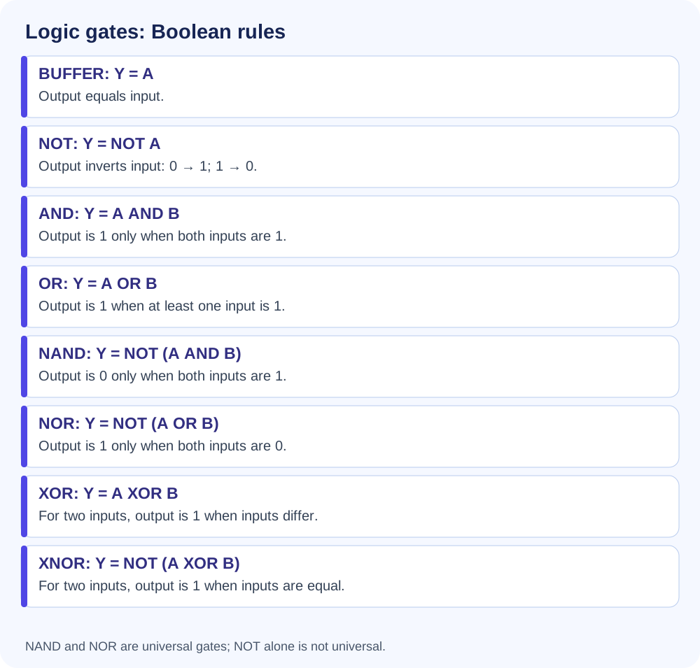
Correct Boolean rules for the eight common logic gates
Basic Logic Gates

ANDNOTOR

Universal Logic Gates

NANDNOR

Other Logic Gates

EX-OR / XOREX-NOR / XNOR
AND Gate
Source rule: output is 1 only if both inputs are 1.
A · B
OR Gate
OR gives 1 when at least one input is 1; it gives 0 only for 00. The + sign denotes Boolean OR.
A + B
NOT / Inverter
Page 15's inverter visual shows a single input changed to its opposite output.
0→1 • 1→0
NAND Gate
Source: opposite of AND; output is 0 only when both inputs are 1.
(A · B)̅
NOR Gate
Source: opposite of OR; output is 1 only if both inputs are 0.
(A + B)̅
XOR Gate
XOR (Exclusive OR) gives 1 when the two inputs differ, and 0 when they are the same.
A ⊕ B
XNOR Gate
Source rule on page 18: output is 1 if inputs are same.
(A ⊕ B)̅
REVISION NOTE
Correct gate rules and tables are shown below. NOT is a basic gate; NAND and NOR are universal gates. XOR means Exclusive OR; XNOR means Exclusive NOR.
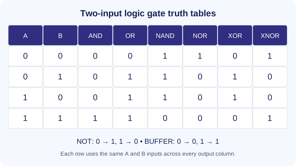
Verified truth tables: AND, OR, NAND, NOR, XOR and XNOR
AND — Truth Table
ABA·B
000
010
100
111
GATE RULE
Output is 1 only if both inputs are 1.
OR — Truth Table
ABA+B
000
011
101
111
EXAM TRAP
OR: at least one input 1 → output 1. Inverting a single input is the NOT operation.
NAND — Truth Table
AB(A·B)̅
001
011
101
110
GATE RULE
Opposite of AND; output is 0 only if both inputs are 1.
NOR — Correct Truth Tablediv>
AB(A+B)̅
001
010
100
110
EXAM TRAP
NOR gives 1 only for 00. For A=1, B=0, its output is 0.
XOR — Truth Table
ABA⊕B
000
011
101
110
EXAM TRAP
XOR = Exclusive OR: different inputs give 1. XNOR = Exclusive NOR: equal inputs give 1.
XNOR — Truth Table
AB(A⊕B)̅
001
010
100
111
GATE RULE
Output is 1 if inputs are same.
NOT / Inverter — Correct Truth TableTruth Table
NOT is a basic single-input gate, not a universal gate. It complements its input: 0 → 1 and 1 → 0.

ANOT A
01
10
d>0
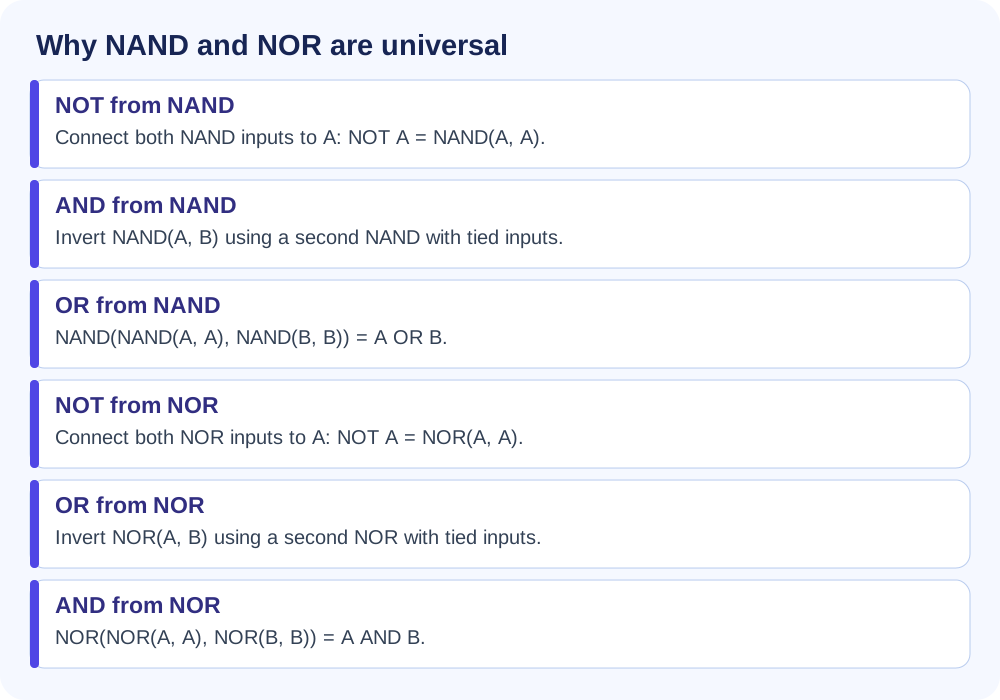
NAND-only and NOR-only constructions of NOT, AND and OR
🧩 Applications of Logic Gates
  • Used in computer processors & circuits.
  • Used in alarm systems & security devices.
  • Used in automatic gates & digital locks.
  • Used in artificial intelligence (AI) and robotics.
Digital Building Block

The chapter frames logic gates as the basic building blocks that perform logical operations on binary 0/1 inputs.

Input → Output Idea

One or more inputs can be accepted, while the output remains a single digital result.

⚡ Quick Recall
  • Logic gates: basic building blocks of digital circuits.
  • Inputs: binary 0 and 1.
  • Basic gates in source: AND, NOT, OR.
  • Universal gates in source: NAND, NOR.
  • Other gates: EX-OR and EX-NOR.
  • AND source table: only 11 gives 1.
  • NAND source table: only 11 gives 0.
  • XNOR source table: same inputs (00, 11) give 1.
EXAM TRAP / SOURCE ALERT
For input order 00, 01, 10, 11: AND = 0001; OR = 0111; NAND = 1110; NOR = 1000; XOR = 0110; XNOR = 1001. NOT complements a single input.